
How to Test a Motorcycle Regulator Rectifier: Step-by-Step
This post contains affiliate links. As an Amazon Associate, we earn from qualifying purchases.
To test a motorcycle regulator rectifier, you need a multimeter and follow a systematic process: check the battery voltage running and not running, then perform a 12-measurement diode test on the disconnected unit. A healthy regulator rectifier converts 3-phase AC from the stator to a steady DC voltage between 13.5V and 15.5V, depending on your bike’s specifications.
If the running voltage at the battery is below 13V or above 16V, the regulator rectifier is likely failing. The definitive test is the diode check, which isolates a bad unit from a failing stator or battery. This isn’t guesswork—it’s matching your meter’s readings to the specific pass/fail thresholds for your motorcycle. For a reliable diagnosis, you must know how to test a motorcycle regulator rectifier.
What follows is the sequence that actually works: starting with the simple battery check anyone can do, moving to the full diode test that catches hidden failures, and finishing with the model-specific numbers you need to make the final call. By the end, you’ll know whether to replace a $50 connector or a $150 part.
Key Takeaways
- Test the battery first. A healthy resting voltage is 12.6V, and a charging system in good shape should show 13.5V to 15.5V at the battery with the engine running at the RPM specified in your manual.
- The 12-measurement diode test is the definitive check for a bad regulator rectifier. You must disconnect the unit and use your multimeter’s diode setting to test for one-way current flow across all three AC terminals.
- Interpret “OL” correctly. On a diode test, OL (Open Loop) means no continuity, which is the expected “no diode” reading for half of the twelve tests. Confusing OL with a failure wastes time and money.
- Match the test to your system. The first diagnostic step is to identify if you have a permanent magnet or stator-controlled system; the wire count from the regulator rectifier tells you which procedure to use.
- Voltage specs are not universal. A Suzuki GSXR-1000 spec is 14.0–15.5V at 5,000 RPM, while a Harley-Davidson procedure may call for over 13.5V at 2,000 RPM. Using the wrong target leads to misdiagnosis.
What a Regulator Rectifier Does (And How It Fails)
A standard regulator rectifier takes the three-phase alternating current (AC) from your motorcycle’s stator and does two jobs. It rectifies that AC into direct current (DC) the battery can use, and it regulates the voltage to prevent overcharging. The target is a steady charging voltage—nominally 13.8 VDC for many systems.
It fails in two main ways. The rectifier diodes can burn out, preventing current from flowing in the correct direction. This causes a no-charge or weak-charge condition. The regulator portion can also fail, either allowing voltage to spike too high (cooking your battery and electronics) or dropping it too low (failing to charge). Overheating is the primary killer, often due to poor airflow, corroded connectors, or a failing stator overworking the unit.
A standard regulator/rectifier takes a 3-phase AC input and converts it to a charging voltage of nominally 13.8 VDC.
You’ll find it bolted to the frame, usually in a location meant for air cooling. It’s a metal box with a multi-pin connector and a thick ground wire. Finding it is step zero.
Symptoms of a Failing Regulator Rectifier
Don’t start testing blindly. These symptoms point directly to a charging system problem, narrowing the focus to the battery, stator, or regulator rectifier.
- Dead or Undercharged Battery: This is the most common sign. You jump start the bike, it runs, but the battery dies again after sitting. The battery itself might be fine, but it’s not being replenished.
- Overcharged Battery: Less common but more destructive. Symptoms include battery fluid boiling over, a swollen battery case, or bulbs blowing frequently. This points to a failed regulator allowing voltage to run wild.
- Flickering or Abnormally Bright Lights: At idle, lights may dim, then surge to extreme brightness as you rev the engine. This indicates unstable voltage regulation.
- Burning Electrical Smell: A failing regulator rectifier often overheats. A distinct, sharp ozone or hot plastic smell from the unit’s location is a dead giveaway.
- The Bike Runs Then Dies: On some systems, a completely failed regulator rectifier can create a short that drains power as you ride, causing the engine to cut out.
If you see one or more of these, it’s time to get the multimeter out. The process is elimination.
The Tools You Actually Need
You need one core tool: a digital multimeter (DMM). Any modern meter from a brand like Fluke, Klein, or even a reliable budget model will work. It must have a Diode Test function (usually denoted by a diode symbol). This function applies a small voltage to check for one-way current flow, which is perfect for testing the rectifier diodes without risking damage.
The research reveals a disagreement on tools for Kawasaki models. The Kawasaki Ninja service manual states you must use only Kawasaki Hand Tester 57001-1394 for resistance tests, warning that other meters may show different readings and that “a megger or a meter with a large capacity battery will damage the regulator/rectifier.” Meanwhile, standard DIY practice documented by sources like OSSA-EFI recommends using a multimeter with a Diode Test function.
Meanwhile, the standard DIY and professional practice, documented by technical resources like OSSA-EFI, is that a standard multimeter with a diode-test function is not only safe but preferable.
| Tool | OEM Stance (Kawasaki) | Community/DIY Standard |
|---|---|---|
| Specialty Tester (e.g., 57001-1394) | Mandatory; other testers may damage unit. | Rarely used or owned. |
| Standard Digital Multimeter | Not recommended; may give false readings. | Standard tool; considered safe and effective. |
For most riders and models, a digital multimeter is the common practical choice. However, for Kawasaki models, the manufacturer warns that only their specific tester should be used to avoid damage and incorrect readings.
Step 1: The Battery Voltage Check
Always start here. This quick test tells you if the charging system is working at all and often points to the next step.
- Set your multimeter to DC Volts (20V range).
- With the bike off, connect the red probe to the battery’s positive (+) terminal and the black probe to the negative (-) terminal. A healthy, fully charged battery should read around 12.6V. Anything below 12.4V is undercharged and needs to be charged before proceeding.
- Start the motorcycle. Let it idle, then bring the RPMs up to the level specified in your motorcycle’s manual for charging system tests. Observe the voltage reading at the battery terminals again.
Where this goes sideways: Testing at idle only. Most charging systems produce minimal current at idle. You must rev the engine to see the regulator’s true output.
Interpreting the Results:
- 13.5V – 15.5V: This is the typical target range. Your charging system is likely functioning. If you’re still having problems, move to the diode test to rule out an intermittent rectifier failure.
- Below 13V (at RPM): The system is not charging. This could be a bad regulator rectifier, a failed stator, or broken wiring.
- Above 16V (at RPM): The regulator has failed and is overcharging. Replace it immediately to save your battery and ECU.
This test isolates the problem to the charging system. The next step is to figure out which component is the culprit.
Step 2: Identify Your System Type
Before you unbolt anything, you need to know what kind of alternator system you have. This changes the diagnostic path. Look at the wire harness coming from your regulator rectifier.
- Permanent Magnet System: Common on older and smaller bikes. The regulator rectifier will have more than 4 wires. Diagnostic focus is on AC output at the regulator rectifier’s input terminals.
- Stator-Controlled System: Common on modern bikes. The regulator rectifier typically has a smaller number of wires, often just the three AC phases. Diagnostic focus is on stator output and then the regulator rectifier’s diode function.
Many diagnostic guides use this wire-count check as the first step in their fault-finding process. Getting this wrong means you test the wrong thing.
Step 3: The 12-Measurement Diode Test (Step-by-Step)
This is the conclusive test for the regulator rectifier’s health. You must disconnect the unit from the motorcycle’s wiring harness for accurate results.
- Locate and Disconnect: Find the regulator rectifier, unbolt it if needed for access, and unplug its main connector.
- Set Your Multimeter: Turn the dial to the Diode Test setting. It may be combined with the continuity beeper.
- Identify Terminals: You’ll see three identical AC input terminals (often yellow wires) and two DC output terminals (Positive + and Negative -). Refer to your service manual for a pinout diagram.
The test involves checking the continuity between each AC terminal and each DC terminal, in both directions. That’s 3 AC terminals x 2 DC terminals x 2 directions = 12 measurements.
Here is the procedure, as specified by OSSA-EFI:
| Measurement | Red Probe To | Black Probe To | Expected Result |
|---|---|---|---|
| 1, 2, 3 | Positive (+) Terminal | AC Terminal 1, 2, 3 | OL (No Diode) |
| 4, 5, 6 | AC Terminal 1, 2, 3 | Positive (+) Terminal | Voltage Drop (0.3V – 0.7V) |
| 7, 8, 9 | Negative (-) Terminal | AC Terminal 1, 2, 3 | Voltage Drop (0.3V – 0.7V) |
| 10, 11, 12 | AC Terminal 1, 2, 3 | Negative (-) Terminal | OL (No Diode) |
What you’re listening for: A diode allows current to flow in one direction (showing a voltage drop) and blocks it in the other (showing OL). If any measurement shows continuity (a beep or very low reading) where it should be OL, or shows OL where it should be a voltage drop, the regulator rectifier is faulty.
Common mistake: Misreading “OL” as a failure. On a diode test, OL is the correct, expected result for half of the measurements. It means the diode is properly blocking current in that direction.
Model-Specific Voltage Specifications
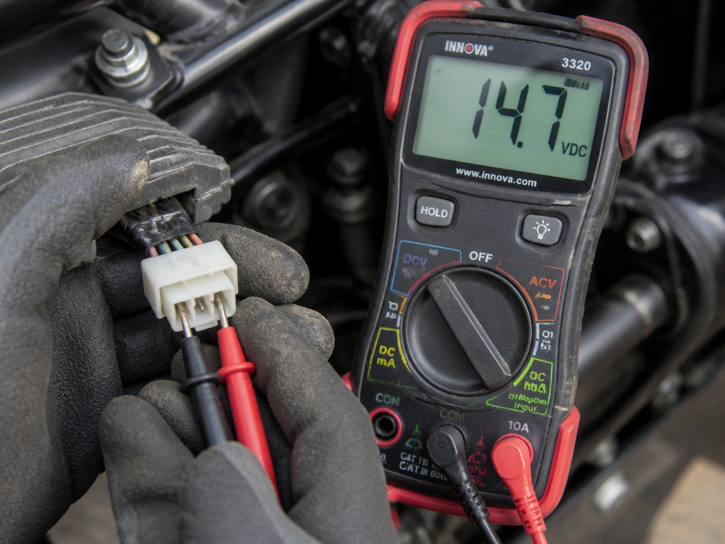
Your bike’s service manual has the final say. Generic voltage ranges get you close, but precise diagnosis needs the right target. Here’s how specs vary:
| Motorcycle Model | Test Condition | Passing Voltage | Source |
|---|---|---|---|
| Suzuki GSXR-1000 | At 5,000 RPM | 14.0 to 15.5 VDC | Fox Motorcycle Institute |
| Harley-Davidson (Evolution) | Per 1,000 RPM (AC) | 16.0 to 20.0 VAC | Fox Motorcycle Institute |
| Harley-Davidson (Touring, FI) | At spec RPM | ~45 Amp capacity | Fox Motorcycle Institute |
| Aftermarket MOSFET (OTK M261) | Constant, any RPM | 15.0 VDC (observed) | OSSA-EFI |
| OE Thyristor Type | Variable with RPM | ~12.6 to 13.1 VDC | OSSA-EFI |
The takeaway is critical. According to one source, an aftermarket MOSFET unit might hold a rock-steady 15.0 VDC, while an older thyristor type might vary between 12.6 and 13.1 VDC. However, the MOSFET unit’s manufacturer specifies an output of 14.5 +/- 0.3 VDC. Knowing which type you have prevents a misdiagnosis of “low voltage” on a healthy older system.
Furthermore, for some models, checking for voltage drop when wiggling the regulator connector can reveal a fault in the connector terminals rather than the unit itself.
What to Do If Your Regulator Rectifier Tests Bad
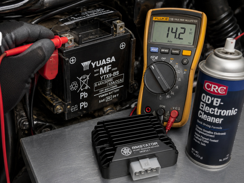
First, check the simple stuff. Clean the unit’s ground connection (where it bolts to the frame) and the connector pins with electrical contact cleaner. A poor ground can mimic a bad regulator.
If it’s truly dead, replacement is your option. You can choose an OEM unit or an aftermarket upgrade. MOSFET units run cooler and often provide more stable voltage, but as the OSSA-EFI data shows, they may output a higher voltage (like 15.0 VDC) than your original equipment. Make sure your battery and electronics can tolerate it.
Before buttoning everything up, repeat the battery voltage check to confirm your charging system is back in the green.
Frequently Asked Questions
How can I test a regulator rectifier without a multimeter?
You can perform a crude “headlight test.” With a fully charged battery, start the bike and turn on the high beam. Rev the engine to a moderate RPM. If the headlight becomes extremely bright (to the point of looking ready to pop), the regulator is likely overcharging. If brightness doesn’t increase much from idle, it may be undercharging. This is not diagnostic—it’s a hint to get a multimeter.
Are all motorcycle regulator rectifiers the same?
No. They differ by the number of phases, amperage output (e.g., 32-amp vs. 45-amp), connector type, and internal technology (thyristor vs. MOSFET). Always match the replacement to your motorcycle’s specifications. Using an under-rated unit will cause it to overheat and fail quickly.
Can a bad regulator rectifier destroy a new battery?
Absolutely. A failed regulator that allows overcharging will literally boil the electrolyte in a conventional battery, warping plates and killing it in a matter of miles. It can also fry sensitive electronics like your ECU or instrument cluster. This is why voltage checks are a critical first diagnostic step.
What does ‘OL’ mean on my multimeter?
In diode test or resistance mode, OL stands for “Open Loop.” It means the resistance is so high the meter cannot measure it—there is no continuity. In the context of the 12-measurement test, seeing OL is the correct, good result for half of the checks. It’s not an error message.
Should I test the stator or the regulator rectifier first?
The most efficient order is Battery -> Regulator Rectifier -> Stator. The battery test is fast. The regulator rectifier diode test is also quick and rules out a very common failure. The stator test (checking AC output and resistance to ground) is often the most involved. This sequence solves most problems before you get to the hardest test.
Before You Go
The real cost of a misdiagnosed regulator rectifier isn’t just the part. It’s the tow, the second battery you cook, and the weekend lost. The 12-measurement diode test is free if you own a multimeter, and it gives you a yes-or-no answer.
One rule some guides skip: for certain models, if the voltage drops when you wiggle the regulator connector, the problem may be in the connector terminals, not the unit. That’s the kind of model-specific trap this guide exists to help you avoid.
Everything above assumes you’ve already done basic checks like a battery test and a fuse check. If those are good, the diode test is your next move. If the regulator rectifier passes, your next step is a full stator test. That’s the sequence—no guessing, just following the voltage.
